Designs for the head had begun.
The STL Viewer was used to demonstrate to one another remotely the models that were worked on over Github.
The advantage of the STL Viewer was remote control of the view of the object, pan and zoom various parts of the object in question thanks to the convenience of the Github viewer.
The disadvantage of the STL Viewer is on the fly changes to the model cannot be made – which in some aspects is a good thing, but when changes have to be made team members would have to communicate what changes could be made before editing the file within a STL editor such as Blender or Fusion 360.
Another disadvantage is a limitation to the dimensions that the website provides – to view the model in it’s entirely would require modelling software such as Blender. Colours are also not included (Surface Model is examined not the textures of the model).

Figure 8 A rendered gear made using Blender (Rendered by Mark Warren)
Figure 9 A STL Model of a rendered gear(Provided by Mark Warren)
Figure 10 A STL Model for a Head Concept (Provided by Mark Warren)
The 3D scanners originally used produced models of a subject that was sitting down/standing up. This required the subject to remain stationary while the scanning took place.
The scanner generates high resolution mesh models which can move during measurements to produce a high-quality scan. With an accuracy of around 0.012-0.025mm (Creaform, 2023). An example of industrial use would be for recording physical attributes of aircraft models for Boeing commercial airplanes (Quality Magazine, 2019). Real life models would benefit the project as human heads are real-life examples: thus, this is practical for use in the projects.
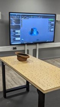
Figure 11 Hat used to render model using Handyscan 3D Scanner (photograph taken by Mark Warren)
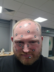
Figure 12 Subject with Scanner Markers placed upon him (photograph taken by Michael Alcock)
The scan while accurate required the use of these 3D Scanner markers. They are small circular discs that are spaced around the object so that the scanner has a reference point in order to recognise an object surface. This would require a minimum of 3 markers with 5 being for the most optimum object surface for 70*100cm space (Thor3D, 2016). While accurate the model could not correctly render the facial hair of the subject, this also meant some facial features were missed due to the limitation of the markers. This made the result not as good as desired more time would be needed to create the mesh of the face to produce a usable model. Also, the lack of colour of the scan meant colour would be applied by hand. Thus, the original colour model produced was not used. The handyscan fired lasers in order to get the geometry of a subject.
Portable scanner which makes use of structured light scanning technology. This uses geometry and texture tracking for full colour scanning and data alignment (Central Scanning, 2020).
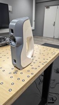
Figure 13 Artec Eva 3D Scanner (photograph taken by Mark Warren)
Another alternative for the 3D Scanner was the Artec 3D Eva Scanner. This was a similar set up as before: instead of standing however, the subject sitting and the scanner would flash the subject with lights and capture the reflection in order to obtain colour. There wasn’t a difference in the quality of standing/sitting but made the process faster than sticking markers on the subject’s head. The model was found to be of a satisfactory quality – while not as accurate, the model did not miss any facial features. These features were then simply smoothed out and holes were cut out from the eye sockets using Blender’s Boolean tool. After smoothing out the hair, a head base could be printed out using a 3D printer.
An Industrial example of the Scanner would be perioperative volumetric assessment of a knee (Latz et al, 2022). Such use of technology can be used to scanned parts of the body to understand the durability of the flesh - hence, this could prove practical for evaluating the model's durability.
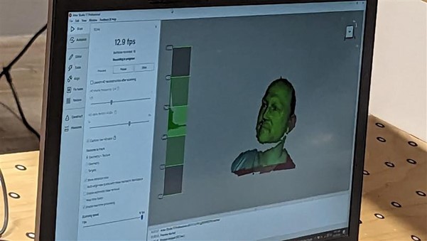
Figure 14 Scanned Subject rendering in Adobe Suite Software (photograph taken by Mark Warren)

Figure 15 Subject being scanned using Artec Scanner from front (photograph taken by Mark Warren)

Figure 16 Subject being scanned Artec Scanner from back (photograph taken by Mark Warren)
After which, the scans were modified through use of Blender.
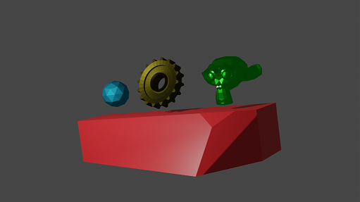
Figure 17 A set of rendered objects made using Blender (Rendered by Mark Warren)
Blender allows for the crafting and modelling of various objects that can be used for things such as animation, game characters or moulding clay to be printed out later on. Blender demonstrates the concepts of the Head model, modification of models would otherwise be too simple in Fusion 360. This software was not really useful for scaling the model but more for the purposes of detailing model characteristics rather than exact measurements for printing the head via a 3D printer this would allow to “mould” the base to better suit the model.
The disadvantage would be that due to how complicated the model is the model had to be simplified to avoid too much geometry for print out. This requires a lot of time as opposed to Fusion 360 and following a lot of tutorials to get the exact result out of the model. Fusion 360 is recommended as Blender is rather complicated to use in comparison.
Objects can be made in blender to provide image files (see figures 18, 19, 20 and 21) – this can be useful for visual concepts. Camera and lighting effects allow to enhance the image whereas otherwise the image would lack shading and textures hence the difference between just a STL file and a rendered image.
An Industrial example of Blender would be using Blender software to develop live 3D models of animals for use in an interactive encyclopaedia (Khan, S. et al, 2019). While practical in an interactive sense, is not useful for the project's design but shows the potential use of demonstrating models to one another.
Figure 18 A rendered gear made using Blender (Rendered by Mark Warren)
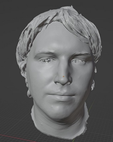
Figure 19 A Mesh edit of Mark's scanned head in blender (Screenshot taken by Mark Warren)
Figure 20 A STL Model of Mark Warren's head modified in blender (Provided by Mark Warren
Figure 21 A STL Model of Mark Warren's head (with no eyes) modified in blender (Provided by Mark Warren
Eyes were cut out (demonstrates blender use case). After developing the concept and discussing at length the ideas of construction, the tools used could be examined in more detail. Please refer to the Detail Section.